| - |
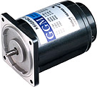
By using it with the speed controller, a wide range of speed can be controlled (50Hz : 90~1400rpm, 60Hz : 90~1700rpm). The speed can be controlled easily with the speed controller. |
| - |
Depending on the type of speed controller, it can be combined with the motor for various purposes such as speed-control, braking, slow run, slow stop, etc. |
| - |
Built in T.G. (Tacho Generator) to control the feedback. Thus, even if the power frequency is changed but the rotating numbers does not change. |
| - |
When the speed control motor with an electronic brake is used with the speed controller, instantaneous braking and electronic braking operate simultaneously for strong braking power. |
| - |
The speed control motor with an electronic brake also has a non-excitation run type of electronic brake. Even if the power is off, braking is operated to maintain braking of a load. |
| - |
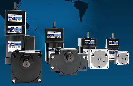
Speed control motors are consisted of the induction motor the reversible motor and the speed control motor with an electronic brake which are small AC motor. The applicable motor should be selected for appropriate uses. |
| - |
Output range of the induction motor is 6W~90W (unit types are 6W~180W). The reversible motor has an output range of 6W~40W and the electronic brake motor has an output range of 6W~40W. (However, SR types are 6W~90W.) |
|
| |

|

- Is speed control needed only?
- Is instantaneous braking needed?
- Is maintenance of braking power needed?
- How much is the output of the applicable motor?
- Are the slow run, slow stop runctions needed?
According to the above conditions, the types of speed control motors and speed controllers are selected.

When the number of rotations of the output shaft of the gear requires A rpm to B rpm, the gear ratio is calculated by using the higher number of rotations (B rpm).
For the AC speed control motor, the number of rotations for the motor is calculated with 1300 rpm. (This is the reason for the output torque and the range of use are large at 1300 rpm.)
 |
Use the nearest approximated value of the gearhead (gear ratio=i) |

| - |
When the highest number of rotations is NH and the lowest number of rotations is NL, they are as follows. |
| - |
Highest number of rotations of the required motor: NH = B x i [rpm] |
| - |
Lowest number of rotations of the required motor: NL = A x i [rpm] |

The required torque of the motor is found as follows.

여기서 TM : Required torque of the motor [g · ㎝]
TL : Torque necessary to operate actual load [g · ㎝]
i : Reduction ratio
η : Efficiency of the gearhead

| - |
The motor is decided by the required torque TM, rotational frequencies NL~NH and the torque-number of rotations curve (hereafter, N-T curve). |
| - |
In the case of the AC speed control motor (Fig. 1) of the curves, the moment curve (i curve) selects the motor below the limit curve. (Even in the area above the limit curve, if the surface temperature of the motor is less than 90℃, then there are no problems with use.) |


| - |
After the motor is selected in the above manner, the gearhead is decided with consideration of the torque size of the load. Confirm that the torque of the load is within the torque allowable by the gearhead. |
|

With single direction rotation of the belt conveyor, change the speed of the item being transported to 1m/minute, 2m/minute, and 4m/minute.
Drum diameter : 10cm
Operating torque : 30㎏ · ㎝
Power : Single phase 110V 60Hz
Instantaneous braking in emergencies, but no holing power.


- Rotation is in one direction and there is no holding power. Therefore, the induction motor is selected.

- The number of rotations of the gearhead shaft when the belt conveyor speed is 1m/minute.

- Number of rotations of the gearhead shaft when the belt conveyor speed is 2m/minute.

- Number of rotations of the gearhead shaft when the belt conveyor speed is 4m/minute.


The gear ratio is calculated using the higher number of rotations of the gearhead.

Using 102, since there is no such reduction ratio as 1/102, 1/100 is selected.

The number of rotations of the motor shaft is calculated by the number of rotations of the gearhead shaft x reduction ratio for each speed of the belt conveyor to get the following.


The transfer efficiency of a gearhead with gear ratio 100 is 66%, so the required torque of the motor is


From the N-T curve of the induction motor, it can be seen that the K8IG25NC-S motor and the K8G100B gearhead can be combined to use. However, in such a case, make sure that the inertia load should fall within the specification of the selected motor. |


| - |
(Fig. 3) is the basic speed control structure of the close loop current control method.
The following are explanations of close loop speed control. |

| - |
If Tacho-Generator changes the voltage that is proportional to the rotations, make comparison between the number of rotations of the motor and the voltage preset by the volume. |
| - |
This difference in voltage is called "comparative voltage". |
| - |
Comparative voltage operates the motor through the boltage amplifier and the voltage controller. |
| - |
Comparative voltage is mostly controlled by zero-crossing. Number of rotations is decided by the value that the speed controller selects. |
| - |
Even when the load changes, the number of rotations does not change. When the Tacho-Generator changes, the number of rotations immediately changes with the value. |
| - |
Accordingly, close loop speed control detects the number of rotations of the motor and controls the operating voltage to maintain it constantly. |

| - |
The relationship between the torque of the induction motor and the number of rotations is as follows (Fig. 4) when the applied voltage (primary voltage) of the motor is changed. |

| - |
The current voltage is V1, the torque of the load is T1 and the number of rotations is N1. That point is A. Speed is increased to B and when the voltage is changed from V1 to V2, then it moves to C. |
| - |
At C, the torque of the load T1 is larger than the torque of the motor, thus the number of rotations are lower than N2. |
| - |
When the number of rotations becomes N3 and the voltage is raised to V3, then the generated torque becomes larger than the torque of the load to move to E, and then the speed increases again toward F. |
| - |
To stabilize the number of rotations, it has to make loop smaller like C→D→E→F by controlling the primary voltage. |
| - |
During the primary voltage control by close loop, to meet the changes according to the number of rotations of the motor, it should have the primary voltage controlled and maintain the number of rotations constant. |


| - |
The speed controller is explained in (Fig. 5). |
| - |
Number of rotations of the motor comes from the Tacho-Generator through feedback voltage through the rectifying circuit. |
| - |
The difference between the selected voltage of the speed controller which was controlled in the VR and the feedback voltage is amplified in the comparative amplifier. |
| - |
A trigger signal is generated from the sawtooth waveform which comes from the sawtooth waveform generator, comparator from the comparative signal and triac from the trigger circuit. |
| - |
The angle of the triac is controlled with the trigger signal to control voltage in the motor. |
| - |
This makes the number of rotations of the motor constant, thereby controlling it. Refer to (Fig. 6). |
 |


| - |
TIn the AC speed control motor N-T graph (Fig. 7), the area below the limit curve is called the continuous operation area. |
| - |
The limit curve does not go beyond the highest temperature allowed by the motor (continuous for induction motors and 30 minutes rating for reversible motors) and because continuous operation is possible, it is decided by the temperature of the motor. |

| - |
Our speed control motor has a class B insulation and the permitted temperature of the winding section is 130℃. Therefore, if the temperature of the winding section is less than 120℃, continuous operation is possible, but it is difficult or the user to measure the temperature of the winding section, continuous operation is generally possible when the surface temperature of the motor housing is less than 90℃. The difference between the winding section of the motor and the housing surface is generally between 10℃~20℃. |

| - |
The highest part of the motor's rising temperature is the winding section. Thus, the highest allowable temperature is decided by the insulation level of the winding section. (Our small AC motor has a class B insulation and the highest allowable temperature is 130℃.) |
| - |
The difference between the temperature of the surface of the motor and the winding section is about 10℃~20℃. (A motor with a cooling fan has about 30℃ because the cooling fan cools the surface of the motor.) |
| - |
When the temperature of the winding section is 130℃, the surface temperature is about 110℃. Therefore, 90℃ is the sufficient value. |

| - |
Instantaneous braking uses direct current which is half-wave rectified current in the motor thus causing the temperature of the motor to rise rapidly. |
| - |
In the N-T graph, the limit curve is in the case of continuous operation, therefore, if instantaneous braking is applied often, the range of the limit decreases. |
| - |
For instantaneous braking, temperature rises by frequent braking, thus care should be taken so that the surface temperature of the motor does not exceed 90℃. |
|
|
 Sign In