PAGE VIEW : 2,230

Product Information :

Name :
TD500
Category :
  1. เครื่องจักร, อุปกรณ์เกี่ยวกับเครื่องจักร, เครื่องมือกล
Sub - Category :
  1. Temperature Controller (Programmable)
Brand :
Hanyoung
Product Type :
  1. สินค้า, ผลิตภัณฑ์

Product Detail :

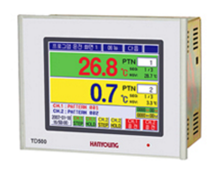
TD500- Touch Panel Color LCD screen

- 2 channels control
- 100 patterns max, 100 segments / pattern(Total 2400 segments)
- PID auto tuning
- Various alarm functions(output : 4 contacts, operation : 20 types)
- Digital input 8 contacts, digital output 16 contacts
- Communication function(RS485 or RS232 depends on the suffix code)


Suffix code

Model Code Information
TD500 - Programmable Temperature controller
Types 1     Communication (RS485 / 422 Communication, USB)
2     Communication (RS232 Communication, USB)
N     None (only when need the I/O (input/ouput board))
Input-Output board 1   Contact input (DI) 8 contacts
Contact output (DO) 8 contacts
Transistor output (DO) 8 contacts
N   Non (Only necessary standard body)
Language   Korean/English (standard type) No code indication
2 English/Chinese (Simplified Chinese Character)

[Monitor specification]
Screen rating Color STN LCD 144.78 mm (5.7")
Number of pixels 320 X RGB X 240
Back light life expectancy

CCFL(approx. 20,000 hrs)

Touch type

Resistive type ( 4 wires)

Language Korean/English or English/Chinese (Simplified Chinese character)
Displaying channel 2 channels (Select the 1 channel and 2 channel indications by the internal selection)

Specification

[Input]
Number of channels 2 channels
Thermocouple input K, J, E, T, R, S
RTD input

Pt 100 Ω (IEC751)

DC rated voltage

0 - 10 V, -10 -20 ㎷, 0 - 100 ㎷
1 - 5 V DC (with 4-20 ㎃ DC, attach 250 Ω external resistance)

Contact input(DI) 8 contacts
Input sampling time Each channel 500 ms
Input impedance Thermocouple/dc voltage (㎷) : 1 ㏁, DC voltage(V) : Approx. 1 ㏁
DC current (4 - 20 ㎃ DC) : attach external resistance 250 Ω
Allowable wiring resistance RTD : max 50 Ω/1 line(same resistance for 3 lines)
Sensor current RTD : 300 ㎂
Detect input disconnection With the input break, it displays "---", Output OFF.
Allowable input voltage DC low voltage (㎷DC) : 5 V DC / DC high voltage (V DC) : 15 V DC
Input compensation ± 100.0 ℃ (Compensation is available for each interval)
Input display resolution 1 digit of decimal point
Memory function Setting and operation information (internal Flash and NVRAM)
R.J.C accuracy Max ± 1.0 ℃
Scaling range -999.9 ~ 9999.9
Insulation resistance Min 20 ㏁. 500 V DC.(input terminal - earth terminal)
Dielectric strength 2,500 V AC. 50 / 60 ㎐ for 1 min (infut terminal - earth terminal)fkls

[Performance]
Display accuracy ±0.1 % of FS ±1 Digit (K, J, E, T)
±0.15 % of FS ±1 Digit (R, S)
±0.1 % of FS ±1 Digit (RTD)
±0.1 % of FS ±1 Digit (DC voltage)
Insulation resistance

Min 20 ㏁, 500 V DC (input terminal - earth terminal)

Dielectric strength

2500 V AC, 50 / 60 ㎐, for 1 min (input terminal - earth terminal)


[Control function and output]

 operation setting
Operation type

program control / Fixed value control selection

Limitation of SV rate change When performing Fixed value control, set the rate of change per min regarding the set value.
Limitation of output rate change Limits an amount of output to become changed no more than 10 % (5% per 0.5 sec)
per second.
Fixation control operation 
time setting
when performing fixed value control, set the operation time
(Set time : 9999 hour 59 min)
Electrical failure backup handling STOP : operation setting, COLD : control again from the beginning, 
HOT : control from the stopped point.
BEEP melody selection Select the Beep melody when operating with touch panel
Touch input lock Limits touch panel operation. 
(With the state of lock, only possible to operate menu button and next button)
Current time / operation time
reservation setting
Set the time of system and the operation time reservation.

 Program setting
Pattern setting

Set the set value and PID group of segment in each patterns, segment time, standby function and time signal.

Segment input/delete Input or delete the segment of each pattern
Time signal setting For the time signal of each segment, select either "segment ON/OFF" or "time operation".
Start/end setting Select among start mode(SSV/PV1/PV2), end(RST/HOLD) mode and end segment
Pattern repetition and connection Set the number of repetition of operation pattern and connection pattern
Segment and number of parts repetitiion.
Standby operation setting Set the standby temperature range of each pattern and standby time.

 System setting
Sensor input setting Thermocouple type / DC voltage input selection and sensor types, input or usable range, input compensation and input filter time.
Control output setting Set the control mode (heating control/cooling control), 
output types (current output, SSR, relay), A.R.W,
output cycle, ON/OFF Control dead zone, output direction (forward/reverse),
current output range and etc
Retransmission output setting Set the retransmission output type of each channel (PV, SV, MV), output range, sensor
break output (0 ㎃, 4 ㎃), current output compensation value of each channel and etc
Inner signal setting Set the each number of inner signal (OFF, 1channel, 2channel), types (TSV, NSV, PV1, PV2), operation range, range direction (inside range, outside range), delay time and etc
Alarm setting Set the observing condition of alarm operation (ALWAYS, RUN, FIX RUN, PROG RUN), 
alarm code of each channel, alarm set value, hysteresis and etc.
P.I.D setting Set the auto tuning gain of each channel, 4 types of PID group and level within each channel, PID auto/manual, auto tuning button (A/T)display, PID integer of each zone, 
dead band and etc
Proportion band 0.0 ~ 1000.0 ℃ ( ON/OFF control when setting with "0")
Integral time 0 ~ 6000 sec
Differential time 0 ~ 6000 sec
OF/OFF control hysteresis 0.1 ~ 1000.0 ℃
Proportional time 1 ~ 1000 sec
A.R.W
(Anti reset windup)
50 ~ 200 % (proportional band)
Amount of output -5.0 ~ 105.0 %
PID Zone 4 group (Level PID)
Digital input (DI)
setting
Set the operation type, standby time, valid point of time, DI name and etc.
Digital output (DO)
setting

Categorize the each signal output by actyal relay or open collector and select output number as for assign output number, alarm output number, time signal 18 contacts output number, input disconnection of each channel, operation of each channel, standby of each channel, hold of each channel, increase interval of each channel, maintain interval of each channel, decrease interval of each channel, contact input Error (DI Error), program end of each channel, I.S 1 and I.S number and output of series(AND) connection, I.S 2 and I.S number and output number of series (AND) etc.

Communication
setting
Set the RS232C or RS485/422 communication function depends on the suffix code
Other setting Language selection (Korean/English, Korean/Chinese), condition of each channel 
(control function,indicate function, not using channel, channel operation at the same time, channel operation individually) selection.

 Control output
Control output Relay Heating and cooling synchronous control (contact output (DO)is applied)
N.O : 250 V AC 5 A, 30 V DC 5 A
N.C : 250 V AC 2 A , 30 V DC 1 A
SCR Heating and cooling synchronous control
Output signal : 4 - 20 ㎃ DC. (load resistance max 600 Ω
Output accuracy ±0.1 % of FS
Temperature drift : ±200 ppm/℃ (output part)
SSR heating and cooling synchronous control
Voltage pulse output : 24 V DC (load resistance min 600 Ω)
Resolving power : smaller one between 0.1 % and 10 ms

 Retransmission output
Retransmission output Output lists Select the Present value (PV), Set value (SV) and output amount of heating
side (H.MV) / output amount of cooling side (C.MV) in each channel
Current output 4 - 20 ㎃ DC (By the scale setting)
Resolving power 16 bits
Output range Setting bound of scaling range
Accuracy ±0.1 % of FS
When performing heating/cooling control and if control output type of cooling side is SCR or SSR then corresponding channel cannot use retransmission output.

 Digital output (DO)
Output number of contact Total 16 contacts (relay : 1c X 4 contacts, 1 a X 4 contacts / open collector : 8 contacts)
Open collector 24 V DC. 300 ㎃ max. (load resistance)
Relay contact N.O side 250 V AC 5 A or 30 V DC 5 A
N.C side 250 V AC 2 A or 30 V DC 1 A
(load resistance)

 Digital output (DI)
Input number of contact Total 8 contacts
Operate the Channels synchronusly 
(1channel / 2channel)
DI-1(RUN/RST)
DI-2~DI-4(RST)
DI-5(STEP/RST)
DI-6(HOLD/RST)
DI-7(HOLD-ON/RST)
DI-8(HOLD-OFF)
Operate the Channels individually
(2channel)
DI-1(CH.1 RUN/CH.1 RST/ERR/RST)
ERROR input active RUN/Always selection
Input signal Non voltage contact input (ON : max 10 Ω, OFF : min 500 kΩ


Other Product In Group "Temperature Controller (Programmable) (3)"