E-Catalog > เครื่องควบคุมมอเตอร์ > Brake Pack
Product Detail :

|
||||||
 |
||||||

Caution of connection 1. - Connections differ with types and output power of the motors. - Connect like diagram A for motor of output power 25W or less - Connect like diagram B for motor of output power 25W to 60W. - B connection and external braking resistor with external resistance of 30Ω 50W / 50Ω 20W is required for motors over 60W. |
||||||||||||||||||||
Operation / Instantaneous Stop - When switch SW2, SW3 are flipped to "RUN", the motor begins to rotate. When these switches are flipped to "STOP", the motor stops instantaneously. Braking current runs through the motor winding for approximately 0.4 seconds and the power is cut automatically. Direction of Rotation - These diagrams all refer CW rotation as viewed from shaft end of the motor. - Do not change direction of rotation 0.4 seconds in inputting power or after braking operation. - In braking operation SW4 and SW5 should necessarily be connected with CW or CCW direction. ※ The capacity of the brake external resistor is the number for the case of one braking in 10 seconds, thus please use the greater capacity for the shorter cycle than this. |
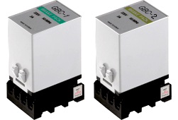
Operation / Instantaneous Stop - When switch SW2, SW3 are flipped to "RUN", the motor begins to rotate. When these switches are flipped to "STOP", the motor stops instantaneously. Braking current runs through the motor winding for approximately 0.4 seconds and the power is cut automatically. Direction of Rotation - These diagrams all refer CW rotation as viewed from shaft end of the motor. - Do not change direction of rotation 0.4 seconds in inputting power or after braking operation. - In braking operation SW4 and SW5 should necessarily be connected with CW or CCW direction. Even when brake pack GBC-1, GBC-2 is used in short operating cycles such as inching operation, the motor can be stopped instantaneously. However, if the motor is operated in a cycle shorter than 0.5 seconds for running and stopping, this will be like repeating starting and instantaneous stopping, and will cause rise of temperature. The temperature of the motor case should be maintained 90℃ and less regardless of operating cycles. |


